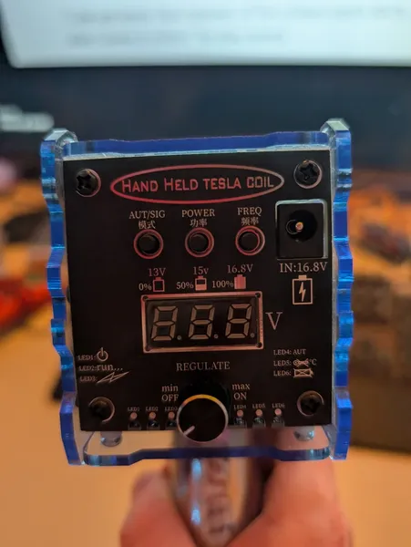
A Hand Held Tesla Coil (model 7N028-V4.0) with a firmware-controlled discharge frequency. The goal: increase that frequency until the arc feels continuous. The path: SWD firmware extraction with a Raspberry Pi, Thumb-mode disassembly, timer register hunting, and fighting OpenOCD's flash driver layer until the right one clicked into place.
The Device
Four 18650 cells in 4S configuration, 16.8V fully charged. Controls are a mode button (AUT/SIG), a POWER button, a FREQ button, and a REGULATE knob running from min/off to max/on. A small display shows voltage with battery percentage indicators: 13V = 0%, 15V = 50%, 16.8V = 100%.
At maximum frequency the discharge runs at roughly 5Hz. Visible, countable, nowhere near the 20-30Hz that would blur into continuous-feeling output. The FREQ button steps through firmware-defined values, so the ceiling is software, not hardware.
PCB Layout
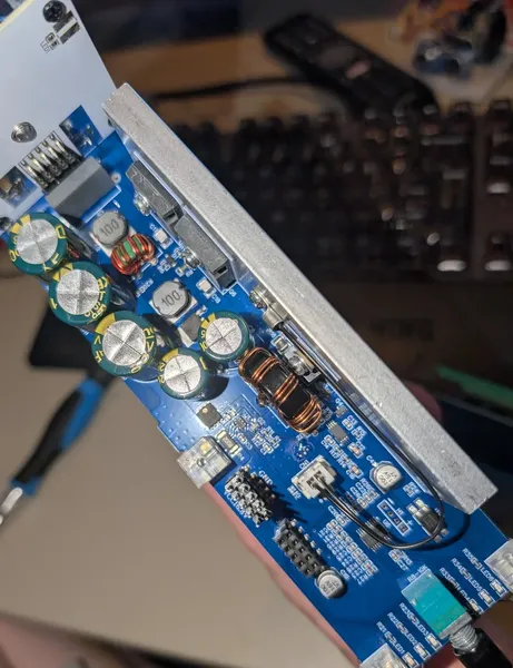
Two boards:
- Main board (blue PCB): five large electrolytic capacitors, toroidal inductors, a copper-wound power inductor, multiple MOSFETs, aluminium heatsink plate. This is the HV discharge side.
- Daughter board (green, marked 7N028-V4.0): a DIP-8 IC, a trimmer potentiometer, an SOT-23 transistor, signal passives, and two white wires back to the main board. This is the control side.
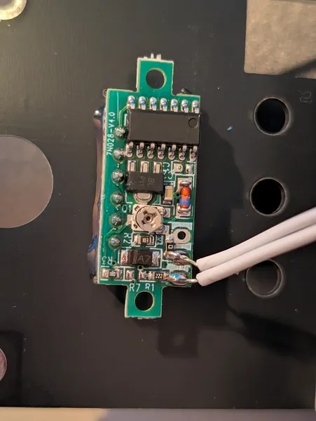
A PC817 optocoupler sits between the two boards, isolating the HV discharge circuit from the control logic. The trimmer pot turned out to adjust the displayed voltage, a calibration offset for the ADC reference, not anything frequency-related.
The main MCU is an AT32F421F8P7: Artery Technology's ARM Cortex-M0+/M4 variant, 64KB flash, up to 120MHz. On the daughter board, a four-pad header labelled H1 with pads marked - x x +.
Finding the SWD Interface
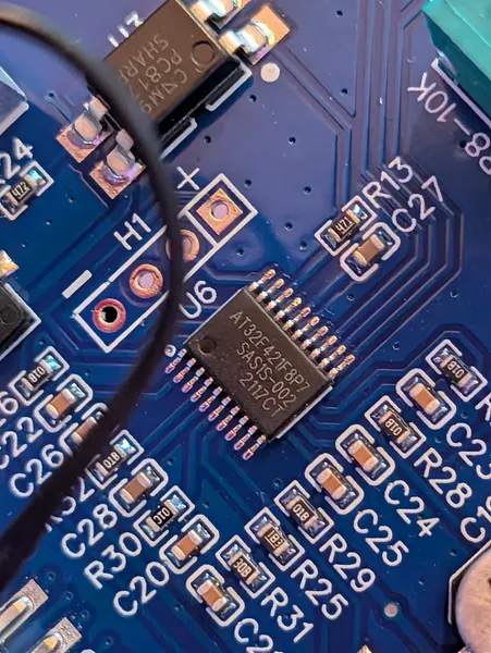
The two centre pads of H1 measured: one at 0V, one idling at 3V. SWDIO idles high. That's the tell. The 3V pad is SWDIO, the 0V pad is SWDCLK. Pin orientation confirmed without a datasheet.
SWD Setup (Raspberry Pi 3B)
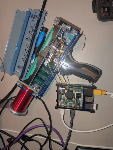
No dedicated programmer needed. The Pi bit-bangs SWD via GPIO:
- GPIO24 → SWDIO
- GPIO25 → SWDCLK
- GND → GND
- VCC left unconnected (coil powered from its own 18650s, Pi powered independently)
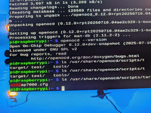
OpenOCD from apt on the Pi ships version 0.12.0+dev-snapshot. First problem: the only Artery config in the package is at32ap7000.cfg. That's an AVR32-based chip using JTAG. Wrong family, wrong transport.
Custom interface config, using current OpenOCD syntax (the old interface / adapter_khz keywords are deprecated):
adapter driver bcm2835gpio
adapter speed 1000

bcm2835gpio_peripheral_base 0x3F200000
bcm2835gpio_speed_coeffs 146203 36

bcm2835gpio_swd_nums 24 25

transport select swd
The peripheral base is 0x3F200000 on a Pi 3B, not the 0x4FE200000 that some older configs list for other Pi models.
Custom target config for the AT32F421:
source [find mem_helper.tcl]
source [find target/swj-dp.tcl]

swj_newdap at32 cpu -irlen 4 -expected-id 0x2ba01477

dap create at32.dap -chain-position at32.cpu

target create at32.cpu cortex_m -dap at32.dap

flash bank at32.flash stm32f1x 0x08000000 0x10000 0 0 at32.cpu
With SWDIO and SWDCLK correctly identified and the Pi peripheral base set right:
SWD DPIDR 0x2ba01477Chip connected and identified.
Dumping the Firmware
telnet localhost 4444
> halt
> dump_image firmware_backup.bin 0x08000000 0x10000
65,536 bytes in 0.67 seconds. Byte-compare verify passed (CRC timeout is normal for AT32; ignore it, run the byte-compare instead). Backup copied off to the main machine before touching anything else.
Binary Analysis
Firmware loaded into Ghidra, ARM Cortex-M Little Endian 32-bit. Immediate problem: Ghidra defaulted to ARM mode instead of Thumb. The disassembly was garbage: coprocessor_function2 and nonsensical instructions throughout. Auto-analysis produced one function. Aggressive Instruction Finder refused to run.
Switching to the command line:
arm-none-eabi-objdump -D -b binary -m arm \
  --force-thumb firmware_backup.bin > firmware.s
--force-thumb is the critical flag. Cortex-M runs in Thumb mode exclusively; without it every instruction decodes wrong.
Then hunting for peripheral register addresses. TIM2 base on ARM Cortex-M is 0x40000000:
grep -n "0x40000000" firmware.sHit at 0x8001e46: mov.w r3, #0x40000000. TIM2 base address being loaded into a register. From there, tracing back through callers:
0x80009d6: bl 0x800206c ; called with r0 = 9The function at 0x800206c contains a switch statement on values 0, 1, 2, matching the three modes selectable via the AUT/SIG button. Inside that function:
0x80021be: ldr r0, [r0, #44] ; @ 0x2cOffset 0x2C into a timer peripheral struct is the ARR (Auto-Reload Register). That's the value that sets the timer period, and therefore the discharge frequency. The frequency calculation loads a base constant from memory, multiplies by a step counter in r4, and writes the result to the ARR.
Extracting the Constants
Two constants referenced in the frequency calculation live at 0x80022a4 and 0x80022a8. Reading them directly from the binary:
import struct

with open("firmware_backup.bin", "rb") as f:
    f.seek(0x22a0)
    data = f.read(16)

for i in range(0, 16, 4):
    val = struct.unpack_from("
0x80022a0: 0x2000007c = 536,870,012 (unrelated)
0x80022a4: 0x007a1200 = 8,000,000
0x80022a8: 0x003d0900 = 4,000,000
0x80022ac: 0x0800267c = 134,227,580 (unrelated)8,000,000 is exactly double 4,000,000. Two frequency step values. Higher ARR value = lower frequency. Halving both values doubles the frequency; quartering them quadruples it.
Two modified binaries prepared with Python:
import struct, shutil

for name, vals in [
    ("firmware_v1.bin", (4_000_000, 2_000_000)),
    ("firmware_v2.bin", (2_000_000, 1_000_000)),
]:
    shutil.copy("firmware_backup.bin", name)
    with open(name, "r+b") as f:
        f.seek(0x22a4)
        f.write(struct.pack("
Flash Driver Problems
First flash attempt using the stm32f1x driver in the target config:
Error: Cannot identify target as a STM32 family.
       Device ID = 0x50020105
       auto_probe failed
The AT32 has its own device ID; the STM32 driver doesn't know it. Manual unlock attempts via telnet (mwh, then mww) with STM32 unlock keys got nowhere (wrong driver, wrong unlock sequence). GDB's restore command was rejected because gdb_memory_map triggered auto_probe on connect, which failed immediately. flash bank can't be issued at runtime via telnet; it has to be in the config before init.
The packaged OpenOCD doesn't have an Artery driver. Building from source does.
Building OpenOCD from Source
git clone https://github.com/openocd-org/openocd.git ~/openocd-src
cd ~/openocd-src
./bootstrap
./configure --enable-bcm2835gpio --enable-internal-jimtcl
make -j4
# ~10 minutes on a Pi 3B
--enable-internal-jimtcl is needed because jimtcl isn't available as a standalone package on Raspberry Pi OS. Without it, configure fails.
After building, the new binary can't find swj-dp.tcl unless you point it at the source tree:
~/openocd-src/src/openocd -s ~/openocd-src/tcl -f interface.cfg -f target.cfgThe -s flag sets the script search path. Without it the binary looks in the installed share directory, which doesn't exist because you didn't run make install.
Searching the source for Artery support:
grep -r "50020105" ~/openocd-src/src/~/openocd-src/src/flash/nor/artery.c: { 0x50020105, "AT32F421F8P7", ... }Device ID 0x50020105 is explicitly listed in artery.c. Updated the target config:
flash bank at32.flash artery 0x08000000 0x10000 0 0 at32.cpuAnd corrected the CPUTAPID to the actual reported value:
swj_newdap at32 cpu -irlen 4 -expected-id 0x2ba01477Successful Flash
With the new binary and the artery driver:
Device ID = 0x50020105 (AT32F421F8P7)
Flash size = 64 KiB
Correct identification. Then:
> program firmware_v1.bin verify 0x08000000
wrote 65536 bytes in 3.68s
verified 65536 bytes in 0.67s
Backup reflash, v1, and v2 all programmed and verified successfully. To restore the backup at any point:
> program firmware_backup.bin verify 0x08000000Result
The v1 and v2 modified firmwares ran on the device. The frequency change was imperceptible in testing.
Correction: The Capacitor Conclusion Was Wrong
The original explanation here was that the capacitor bank was the real bottleneck: halving the timer values just fired the trigger into a half-charged bank, producing the same arc rate at lower energy. This is incorrect and is retracted.
The evidence came from testing v4 firmware, which reduced the counter threshold at 0x8000a8c from 735 to 200. The arcs were weak, but the first arc after power-on was also weak, before any recharge issue could apply. At power-on, the caps are fully charged. A weak first shot means cap recharge time is not the gating factor. Something in the firmware was directly controlling arc energy, independent of the capacitor state.
The reason v1 and v2 showed no perceptible frequency change is explained below.
What the ARR Constants Actually Control
The constants at 0x80022a4 (8,000,000) and 0x80022a8 (4,000,000) do feed into a timer ARR via the function at 0x800215c. However they set the period of a timer that is not the direct discharge trigger. Patching them changes something in signal or mode timing but does not change the rate at which arcs fire. That is why v1 and v2 were imperceptible.
One additional detail from the analysis: a right-shift lookup table at 0x0800267c holds the values [0,0,0,0,0,0,0,0,1,2,3,4,6,7,8,9], indexed by a 4-bit field from the timer register. This table applies a final divisor to the ARR constant before writing it to the timer. For indices 0 through 7 the shift is 0, so there is no effect in those modes. It appeared significant during analysis but turned out to be a red herring for frequency control.
The Two-ISR Architecture
Tracing the vector table revealed two ISR handlers that together drive the discharge cycle:
ISR at 0x8000a4c (IRQ vector 25): pulse width
This ISR increments a counter and compares it against a threshold of 735, encoded as movw r1, #735 at flash offset 0x8000a8c. When the counter hits 735, it calls a GPIO write function at 0x8001be4 that clears a GPIO pin, ending the discharge pulse, then resets the counter. This ISR controls how long each individual arc lasts. Reducing the threshold to 200 shortened the ON time, delivering less energy per arc regardless of cap charge state. That is exactly why the first shot after power-on was weak.
ISR at 0x800129c (IRQ vector 36): discharge frequency
This ISR runs a two-level counter structure. An inner counter increments and compares against 3000 (movw r1, #3000 at 0x80012c4). When the inner counter hits 3000, the outer counter increments and the inner resets. When the outer counter hits 10 (cmp r0, #10 at 0x80012e0), the GPIO pin is set to start a new discharge pulse and both counters reset. Effective threshold per discharge: 3000 x 10 = 30,000 ISR ticks. This ISR controls how often a new arc begins.
The Correct Patch (v6)
To double discharge frequency, patch the 3000 threshold in the second ISR to 1500, and the midpoint comparison at 0x8001300 from 1500 to 750. Both are Thumb-2 movw immediate encodings:
0x80012c4: f640 31b8  (movw r1, #3000)  ->  f240 51dc  (movw r1, #1500)
0x8001300: f240 51dc  (movw r1, #1500)  ->  f240 21ee  (movw r1, #750)
This is what v6 implements. With the device already running at roughly 13.5Hz at max FREQ setting, halving the threshold pushes it toward 27Hz, at or above the perceptual fusion threshold where individual arcs begin to feel continuous. Testing confirmed increased frequency with full arc strength maintained, which also confirms that capacitor recharge time was never the bottleneck.
Next Target: Auto-Boot at Maximum Power and Frequency
Further analysis confirmed that both POWER and FREQ buttons are step incrementers, not toggles. Each press increments a RAM counter by one. Neither reads GPIO pin state in a loop. This means the device has no concept of "on" vs "off" baked into hardware logic: it reads counter values from RAM, and those counters can be written at init.
The goal: patch the init function at 0x8000978 to write maximum counter values at startup, so the device boots directly into maximum power, maximum frequency, actively discharging, with no button presses required.
Finding the Counters via Live Memory Diffing
The FREQ counter maximum is already known to be 10, from the cmp r0, #10 instruction at 0x8000ea4 found during ISR analysis. The POWER counter maximum and the RAM addresses of both counters still need to be located. Live memory diffing via OpenOCD is the right approach.
With the device running, read a region of RAM, press the target button once, read again, and diff:
halt
mdh 0x20000000 64
resume
Press FREQ once, then immediately:
halt
mdh 0x20000000 64
resume
Any halfword that changed by exactly 1 is the FREQ counter. Repeat independently for POWER. Keep pressing POWER and reading until the value stops incrementing to find its maximum. A third address to look for: a discharge-enable flag, a halfword that flips from 0 to 1 when both counters are above 0 and the device starts firing. This will also appear in the diff.
Patching Init
Once all three addresses are known, the init function gets store halfword instructions inserted to write the max values directly:
- FREQ counter address written to 10
- POWER counter address written to its maximum step value
- Discharge enable flag written to 1, if a separate flag exists
The button handlers only increment the counters; they do not reset them on each loop iteration. The ISRs read counter values and use them to scale behaviour; they do not re-read hardware pin state. A value written at init persists. The patch is sufficient without touching the ISRs themselves.
Why the NOP Approach Failed
An earlier attempt patched the branch at 0x8000a5a in the discharge ISR to a NOP, bypassing what appeared to be a power gate check before the call to 0x8001b20. It had no effect. The likely reason: 0x8001b20 reads a peripheral register (GPIOA base at 0x40020000) rather than a RAM flag, so that particular check is a hardware GPIO read. The NOP bypassed it, but counter-based guards deeper in the ISR call chain remained intact and continued blocking discharge.
The live diff approach bypasses the guesswork entirely. All relevant addresses will appear unambiguously in the before/after comparison in a few minutes of button pressing.
What's Next
- Run the live memory diff to locate the FREQ counter, POWER counter, and discharge-enable flag addresses
- Patch init to write max values at boot
- Explore the SIG input mode, which takes an audio signal and modulates discharge on it, a different code path entirely
Tools
- Raspberry Pi 3B: SWD programmer via GPIO bit-banging
- OpenOCD (compiled from source): SWD interface and flash programming; packaged version lacks the artery driver
- arm-none-eabi-objdump: Thumb-mode disassembly with
--force-thumb - Ghidra: initial analysis attempt; useful for the vector table but defeated by ARM/Thumb auto-detection
- Python3 struct: raw binary constant extraction and patch writing
- Multimeter: SWD pad identification by voltage
> End of output.